Settings, Troubleshooting, FAQ and Glossary
This chapter documents the Settings Center of the Mikrofab semiconductor / thin-film transistor (TFT) / photovoltaic (PV) measurement and analysis software setting by setting, provides step-by-step solutions for the most common problems, answers frequently asked questions, and explains the technical terms and abbreviations used throughout measurement and analysis. The Default column in the tables is taken verbatim from the factory values in the config/default_config.json file shipped with the software; you can confirm a value here before changing it.
Ctrl+,. The page consists of a category navigation on the left, a search box at the top, the form panel of the selected category on the right, and a Save / Apply / Cancel / Reset to Defaults button bar at the bottom.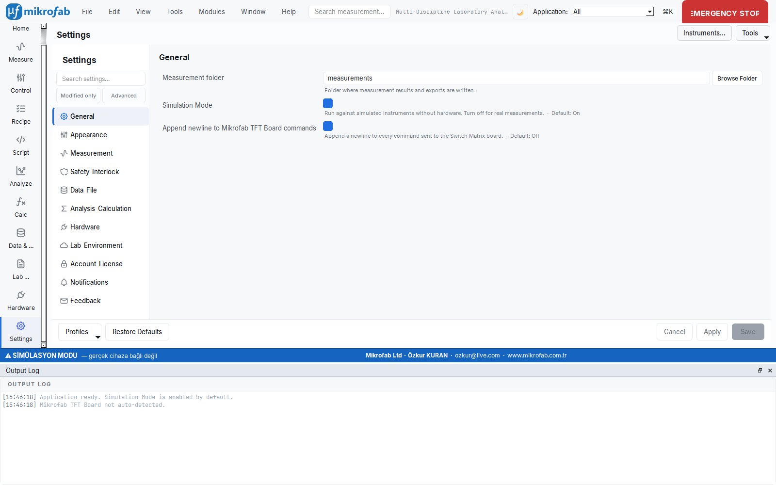
This section is like the "back of the user manual": you look here for what a setting does and its factory value, what to do when an error appears, and what the abbreviations you encounter (Vth, FF, EQE…) mean. It is the first place to look when something does not work as you expect; think of it as the thick reference booklet that comes in the instrument's box — instead of reading it cover to cover, you open it when you need it.
- Why it is done: to configure the software safely, quickly resolve where you got stuck, and learn the technical terms.
- What it teaches / measures: the meaning of each setting + its factory default, step-by-step solutions for common problems, FAQ and a technical glossary.
- Where it is used: first-time setup, changing settings, troubleshooting errors/faults, and looking up terms while reading reports/results.
1. Understanding the Settings Center — The Save Model
The Settings Center does not write your changes to disk immediately; it first accumulates them in a draft and commits them when you press Save. This way you do not accidentally make a wrong value permanent — it is like reviewing a form before pressing "Submit". Theme/font/language are the exception: they are previewed instantly, but are still not written to disk until you Save.
- Why it is done: to prevent hardware-sensitive settings from being changed silently or by accident.
- What it teaches / measures: which change is "pending" (dirty ●), which is a live preview, and how to undo it.
- Where it is used: on every settings change; especially for critical settings such as Simulation Mode that alter device behavior.
The Settings Center uses a hybrid (staged) save model. This is designed to prevent hardware-sensitive settings from being written accidentally and silently.
| Behavior | Description |
|---|---|
| Staging | Every change you make is first written to a working copy; it is committed to the live configuration only when you press Save. |
| Live preview (live) | Settings marked live, such as theme, font and language, are previewed the moment you change them (applied on screen immediately) but not written to disk. They are reverted with Cancel. |
| Dirty indicator | If there are unsaved changes, a * appears in the page title and a ● unsaved changes badge appears in the bottom bar; an ↺ (undo) button appears on each changed row. |
| Validation | If a numeric field is outside the allowed range, a red error message appears below the row and the Save button is disabled. |
Button bar
| Button | Function |
|---|---|
| Save | Makes the staged changes permanent (enabled only when there are changes and they are valid). |
| Apply | Saves without leaving the page. |
| Cancel | Reverts all changes (and live previews) to the last saved state. |
| Reset to Defaults | Returns all settings to the factory defaults (asks for confirmation; Save is still required to make it permanent). |
| Profiles | Save/load/delete named settings snapshots; Export/Import to a file (*.json). |
2. Settings Reference (Category by Category)
The tables below give, for each setting, its display name → configuration key (config key), meaning, valid values and factory default. For numeric settings, the unit and the allowed lower/upper limit are also stated.
2.1 General
The General tab determines the most fundamental behaviors of the software: where results will be saved, whether you will work with a real device or with mock (simulation) devices, and how much detail will be written to the log. This is the first place a new user visits; in particular Simulation Mode is the switch that must be turned off when moving to real measurements.
- Why it is done: to set up the software for your lab layout and choose the real/trial operating mode.
- What it teaches / measures: basic keys such as the output folder,
mock_mode, Switch Matrix line-ending and log level. - Where it is used: first-time setup and the transition from simulation to real hardware.
| Setting (key) | Meaning | Values | Default |
|---|---|---|---|
Measurement folder (output_directory) | Folder where measurement results and exports are written | Folder path | measurements |
Simulation Mode (mock_mode) | Work with mock devices without hardware; turn off for real measurements | On / Off | On (true) |
Switch Matrix newline (switch_append_newline) | Append a line ending to the end of every command sent to the Mikrofab TFT/Relay board | On / Off | Off (false)¹ |
Log level (log_level) — Advanced | Detail level written to the log file; applied after restart | DEBUG / INFO / WARNING / ERROR | INFO |
default_config.json the top-level switch_append_newline key comes as true; however, the descriptive default of the control in the General panel is false. The actual behavior follows the saved configuration value. Leave it off if the command sent to the real board does not expect a line ending.live action; because it changes device behavior it is staged and takes effect only with Save.2.2 Appearance
The Appearance tab sets how the interface looks and which language it is in: light/dark theme, font, application and help language, plus interface complexity by role. These do not change the measurement result, they only improve your working comfort — it is like adjusting the seat and mirrors to suit yourself while driving the same car.
- Why it is done: to make the interface comfortable to work with, suited to your eyes and language.
- What it teaches / measures: theme, font, language/guide language, user mode and plot grid.
- Where it is used: personal preference; training/presentation (simple mode) or advanced use (expert/developer mode).
| Setting (key) | Meaning | Values | Default |
|---|---|---|---|
Theme (theme) | Light or dark interface theme; applied instantly | light / dark | light² |
Font (ui_font_family) | Interface font family; empty = embedded Inter | Any installed font (embedded: Inter, Geist) | "" (Inter) |
Language (language) | Application interface language; applied instantly | tr / en | en |
Guide language (guide_language) | Language of help and guide texts | tr / en | en |
User mode (user_mode) | Adjusts interface complexity by role; takes effect after restart | operator / simple / expert / developer | expert |
Plot grid (plot_show_grid) | Show guide grid lines on plot axes | On / Off | On (true) |
dark, while the factory configuration is light. Which theme appears at startup depends on the saved theme value.2.3 Measurement
The Measurement tab determines the default behavior of the measurement panels: how numbers are displayed, which SMU channel is connected to drain/gate, and which current/voltage/time values new measurements start with. If you define the correct "starting values" once here, you avoid entering the same settings by hand for every new measurement.
- Why it is done: to set up recurring measurements consistently and quickly; to predetermine the noise/speed balance.
- What it teaches / measures: number format, channel mapping and central SMU defaults (compliance limit, NPLC, settling time…).
- Where it is used: setting up the lab's standard measurement recipe once and spreading it to all panels.
Number format and readout
| Setting (key) | Meaning | Values | Default |
|---|---|---|---|
Data entry number format (input_number_format) | Display format of numbers in input fields | 2/4 decimals × engineering / scientific / fixed | 2-Engineering |
Graph axis number format (graph_number_format) | Format of numbers on graph axes | (same options) | 2-Engineering |
Readout panel decimals (readout_decimals) | Decimal places of values in the right Readout panel; the report is not affected | Integer 0–6 | 2 |
Open Readings window on measurement start (reading_window_autoopen_on_start) | Automatically open the floating Readings window when a measurement begins | On / Off | Off (false) |
2-Engineering, 2-Scientific, 2-Fixed, 4-Engineering, 4-Scientific, 4-Fixed. "Engineering" keeps exponents at multiples of 3 (compatible with SI prefixes: n, µ, m, k, M…), "scientific" uses a single-digit mantissa, and "fixed" shows decimals without an exponent.Channel mapping
| Setting (key) | Meaning | Values | Default |
|---|---|---|---|
Drain SMU (smu_mapping.drain) | SMU channel assigned to the drain terminal | Channel A / Channel B | a (Channel A) |
Gate SMU (smu_mapping.gate) | SMU channel assigned to the gate terminal | Channel A / Channel B | b (Channel B) |
Central SMU defaults
Central SMU defaults (default_smu.*) — new measurement panels seed their relevant inputs from these values:
| Parameter (key) | Unit | Range | Description | Default |
|---|---|---|---|---|
Current compliance (current_compliance) | A | 0 – 1 | Default SMU current compliance limit | 0.0001 (100 µA) |
Voltage limit (voltage_limit) | V | 0 – 210 | Default voltage limit | 20.0 |
Power limit (power_limit) | W | 0 – 22 | Default power limit | 2.0 |
NPLC (nplc) | PLC | 0.01 – 25 | Integration time; high = low noise, slow | 1.0 |
Settling time (settling_time_s) | s | 0 – 10 | Wait after the source is set, before measuring | 0.05 |
Measurement delay (measurement_delay_s) | s | 0 – 10 | Additional delay between each measurement point | 0.02 |
Averages (averages) | — | 1 – 100 | Number of readings averaged per point | 1 |
1 PLC (20 ms at 50 Hz) is a good balance for most DC measurements; for noise at low currents you can increase it to 10 PLC.2.4 Safety & Interlock
This panel shows the absolute voltage/current/power ceilings the measurement engine will never exceed; it exists to reject a request that could burn the sample or the instrument before it is even sent. It is read-only so it cannot be changed by accident — think of it like a fuse in a circuit: normally invisible, but it cuts the circuit if something goes too far.
- Why it is done: to prevent sample and instrument damage and dangerous overload.
- What it teaches / measures: the highest allowed absolute voltage, current compliance and power limits.
- Where it is used: setup safety; the factory values are effectively unlimited and should be tightened from the configuration file in a real lab.
This category is an information panel (not a form). The limits below are enforced at the hardware level by the measurement engine and are read-only here so they cannot be changed by accident. To change them, the advanced configuration file is used.
| Limit (key) | Meaning | Factory value |
|---|---|---|
Max. absolute voltage (safety_limits.max_abs_voltage) | Highest allowed absolute voltage | 1 000 000 V (effectively unlimited) |
Max. current compliance (safety_limits.max_current_compliance) | Highest allowed current compliance | 1 000 000 A (effectively unlimited) |
Max. power (safety_limits.max_power) | Highest allowed power | 1 000 000 W (effectively unlimited) |
2.5 Data & File
This setting determines which file types are produced when a measurement is saved (CSV, TXT, Excel, HDF5). You choose based on which program you will process the results with — xlsx if your colleague uses Excel, csv if you will process it with your own script; you can select more than one at the same time.
- Why it is done: to export results in a format compatible with the tools you will use.
- What it teaches / measures: the active export formats (
export_formats) and the default selection. - Where it is used: data sharing, archiving and external analysis workflows.
| Setting (key) | Meaning | Values | Default |
|---|---|---|---|
Data format (export_formats) | File formats produced when saving/exporting (multiple may be selected) | CSV, TXT (tab-separated), Excel XLSX, HDF5 (.h5) | ["csv","txt","xlsx"] |
.xlsx uses openpyxl; if it is not installed, the software produces a minimal Excel file with the standard library. HDF5 requires the relevant library.2.6 Analysis & Computation
The Analysis workspace extracts metrics (e.g. temporal-response times) from the measurement files you have saved; this tab sets that workspace's defaults — which module comes pre-selected, where files are imported from, and at what percentages the temporal-response thresholds are. If you make the analysis type you use most the default, you start with a single click on every launch.
- Why it is done: to speed up repeated analyses and work with consistent thresholds.
- What it teaches / measures: the default analysis module, the import folder and the lower/upper threshold percentages (10%/90%).
- Where it is used: extracting metrics from loaded data; the routine analysis flow.
| Setting (key) | Meaning | Values | Default |
|---|---|---|---|
Default analysis module (analysis.default_module) | The module pre-selected when the analysis workspace opens | One of the registered analysis modules | temporal_response |
Related keys (not visible in the panel, present in the JSON):
| Key | Meaning | Default |
|---|---|---|
analysis.import_directory | Folder for files imported for analysis | analysis_imports |
analysis.default_threshold_low_pct | Lower threshold (%) in temporal-response analysis | 10.0 |
analysis.default_threshold_high_pct | Upper threshold (%) in temporal-response analysis | 90.0 |
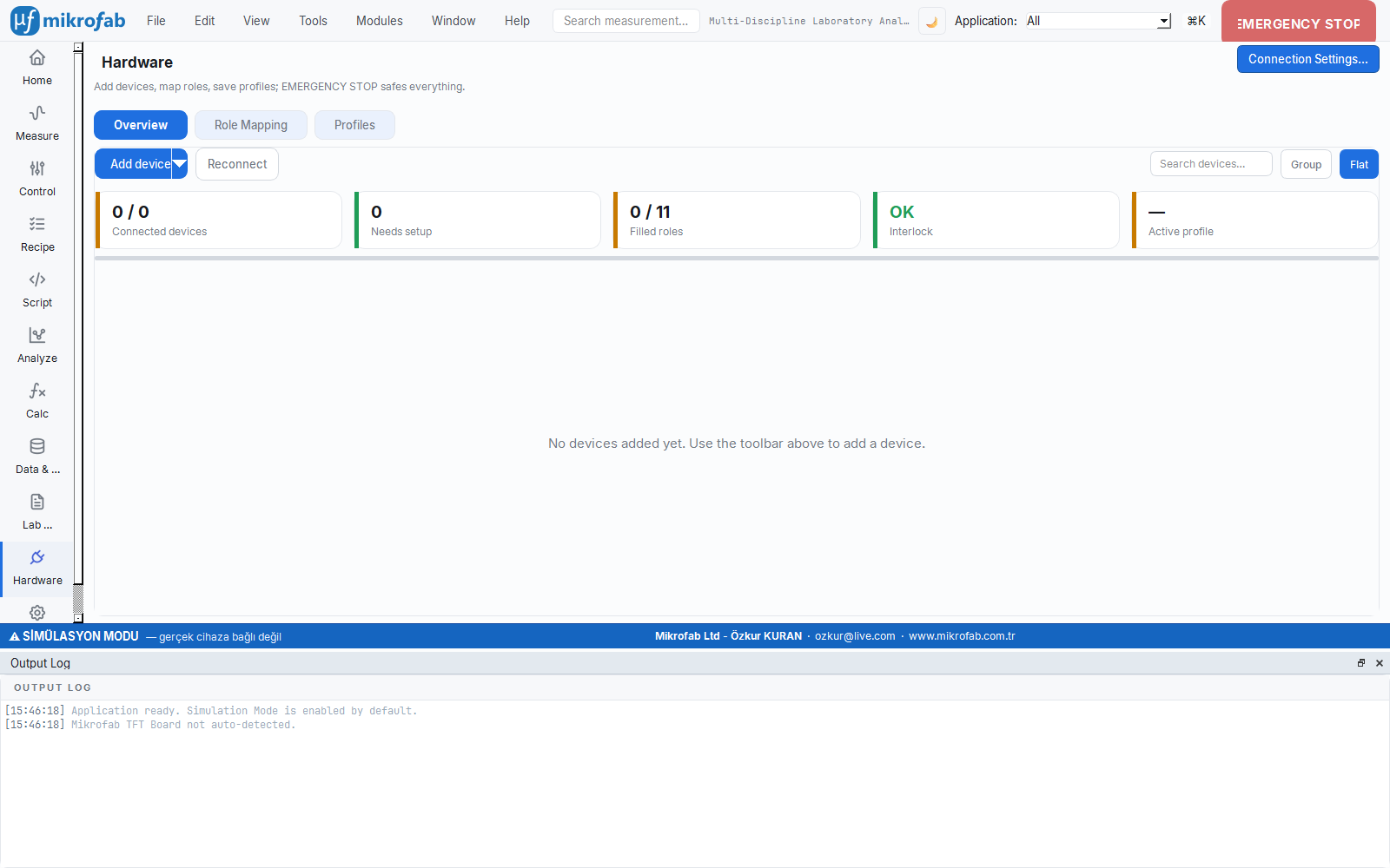
2.7 Hardware
The Hardware tab defines how the software talks to real instruments: the VISA address to connect to, the connection timeout, and calibration tracking. Here you tell the computer which instrument to find and where — like saving the instrument's number in a contact list.
- Why it is done: to connect correctly and reliably to devices such as the SMU and relay board.
- What it teaches / measures: the VISA resource/timeout, SMU setup mode, switch port and calibration reminder.
- Where it is used: real hardware setup and troubleshooting connection problems.
| Setting (key) | Meaning | Values | Default |
|---|---|---|---|
VISA resource (visa_resource) | VISA address string of the device to connect to | E.g. GPIB0::24::INSTR, TCPIP0::192.168.1.10::inst0::INSTR | "" |
VISA timeout (visa_timeout_ms) — Advanced | Timeout for device polling/connection testing (a device-specific value takes precedence) | 100 – 60 000 ms | 3000 |
Calibration reminder (calibration_reminder_enabled) | Write a warning to the log at startup when the calibration period has expired | On / Off | Off (false) |
Last calibration date (calibration_last_date) | Date of last calibration (YYYY-MM-DD) | Date text | "" |
Calibration interval (calibration_interval_days) — Advanced | Number of days between two calibrations | 1 – 3650 days | 365 |
At the bottom of the Hardware panel, the Instruments… button opens the Instrument Registry dialog (see §2.12). Advanced hardware keys present in the JSON:
| Key | Meaning | Default |
|---|---|---|
smu_setup_mode | SMU setup mode | dual_channel |
dual_channel_model / dual_channel_resource / dual_channel_connection_type | Dual-channel SMU model, VISA address, connection type | 2614B / "" / USB (USBTMC) |
smu1_*, smu2_*, diode_smu_* | Single/diode SMU model + resource + connection | 2450 / "" / USB (USBTMC) |
switch_port / switch_baudrate | Switch Matrix COM port and baud rate | "" / 9600 |
relay_enabled | Relay/Switch Matrix control enabled | true |
selected_tft, tft_mapping | Selected TFT and TFT → relay command mapping | TFT 1 / 5-entry table |
2.8 Lab & Environment (Weather)
This feature shows the outdoor weather in a small badge based on the location of the lab you work in. It does not directly affect the measurement; but in sensitive measurements where ambient conditions such as temperature/humidity can influence the results, it is a practical reminder to keep the conditions at the time of recording in mind.
- Why it is done: to keep ambient conditions in mind and for daily working comfort.
- What it teaches / measures: weather-badge settings such as location, latitude/longitude and refresh interval.
- Where it is used: context in environment-sensitive measurements; an optional convenience.
| Setting (key) | Meaning | Values / Range | Default |
|---|---|---|---|
Show weather (weather.enabled) | Enable the outdoor weather badge | On / Off | Off (false) |
Location (city) (weather.location_name) | Weather location name (city/district search) | Text | "" |
Latitude (weather.latitude) — Advanced | Geographic latitude | −90 … 90 ° | 0.0 |
Longitude (weather.longitude) — Advanced | Geographic longitude | −180 … 180 ° | 0.0 |
Refresh interval (weather.refresh_minutes) — Advanced | How often the weather data is refreshed | 5 … 720 min | 30 |
Related JSON key: weather.timeout_s (network timeout, default 8.0).
2.9 Account & License
This panel shows the software's license status and is where you activate it: you copy the Machine ID and send it to the vendor, then paste and activate the license key you receive. Without a license, real-device measurements are limited; simulation mode, on the other hand, is always unlimited.
- Why it is done: to unlock/authorize the full version of the software for real measurements.
- What it teaches / measures: the Machine ID, license status (Active/Unlicensed) and remaining trial allowance.
- Where it is used: first purchase/activation and license renewal.
This category is an information/action panel that shows license activation directly within settings:
- Machine ID: Device-specific identifier; copied to the clipboard with Copy (sent to the vendor to obtain a license).
- Status: Active (green) or Unlicensed (red) + remaining trial measurement allowance. Simulation mode is unlimited.
- License Key: Paste the key in
PAYLOAD.SIGNATUREformat and press Activate License.
Related JSON key: license_check_online (online license check, default true).
2.10 Notifications
This tab manages the software's two limited contacts with the outside world: anonymous usage telemetry and new-version checking. Telemetry sends only anonymous events such as "which setting changed"; raw measurement data, values or serial numbers are never sent — you can turn it off with a single click if you wish.
- Why it is done: to make an anonymous contribution to the software's improvement and stay up to date; you decide the privacy preference.
- What it teaches / measures: the on/off state of telemetry and update checking (and the related JSON keys).
- Where it is used: turning off telemetry for privacy; stopping update checks on offline/air-gapped networks.
| Setting (key) | Meaning | Values | Default |
|---|---|---|---|
Send anonymous usage data (telemetry_enabled) | Send anonymous usage telemetry; raw data/serial number is never sent | On / Off | On (true) |
Update check enabled (update_check_enabled) | Check at startup whether a new version is available | On / Off | On (true) |
Telemetry / privacy — JSON keys
| Key | Meaning | Default |
|---|---|---|
telemetry_endpoint | Telemetry event endpoint | https://telemetry.mikrofab.com/api/events |
telemetry_batch_size | Number of events collected in a single submission | 50 |
telemetry_timeout_s | Telemetry network timeout | 3.0 |
telemetry.install_id | Anonymous installation identifier | "" |
environment | Runtime environment label | beta |
glitchtip_dsn / sentry_dsn | Error-tracking endpoints | GlitchTip filled / Sentry empty |
Update — JSON keys
| Key | Meaning | Default |
|---|---|---|
update_manifest_url | Version notification (manifest) address | https://download.mikrofab.com/suite/latest.json |
update_check_interval_hours | Update check frequency | 24 |
update_timeout_s | Update check timeout | 8.0 |
update_skip_version | Version to skip | "" |
info_feed_enabled / info_feed_url / info_feed_timeout_s | Announcement feed enabled / address / timeout | true / announcement URL / 8.0 |
2.11 Feedback
This form lets you send a suggestion, bug or question that occurs to you while using the software directly to the developers — without leaving the application, optionally attaching a file such as a screenshot. The user who experiences a bug describes it best; that is why the feedback that comes from here plays a direct role in improving the software.
- Why it is done: to record problems and requests and deliver them to the developers.
- What it teaches / measures: the category, rating, message, contact and attachment fields.
- Where it is used: bug reporting, feature requests and sharing general opinions.
This category shows the feedback form directly within settings: category (suggestion/bug/question/other), rating (1–5 or none), message, contact (optional) and attachment (≤ 5 MB). It is submitted with Send Feedback.
2.12 Instrument Registry
The registry gathers all the instruments in your lab into a single inventory: you define each instrument once with an understandable name, and measurements refer to it by that name. If an instrument's address changes, you update only here and all measurements adapt automatically — like the contact list on your phone: when a number changes you update the contact, you do not retype the number on every call.
- Why it is done: to manage device addresses from one place and abstract measurements away from hardware detail.
- What it teaches / measures: the device's type, model, VISA address and connection form; connection testing with
*IDN?. - Where it is used: multi-instrument setups, address changes and connection verification.
The Instruments… button in the Hardware category (or the same button in the top bar) opens an NI-MAX / KickStart-style instrument inventory. The logic: you define a device once (understandable name + type + model + VISA address + connection), and measurements refer to it by name. When the address changes, you update it only here.
| Field | Values |
|---|---|
Type (itype) | SMU · Relay/TFT Board · LCR · Other |
| Model | Known model keys (dropdown) or free text |
Address (VISA) (resource) | VISA resource string |
Connection (connection) | USB (USBTMC) · GPIB · LAN (TCPIP) · RS-232 (Serial) |
- Manage the inventory with Add / Edit / Delete.
- The Test (*IDN?) button verifies the connection with a
*IDN?query without running a measurement; the result appears as ✓/✗ in the row's Status column (it also works in simulation mode).
user_config.json file, and "Raw configuration (JSON)" lets you inspect the merged configuration read-only.3. Troubleshooting
The table below summarizes the most common problems and their solution steps.
3.1 Device not found / cannot connect
- Is Simulation Mode on? If
mock_modeis on in the General tab, the software never connects to a real device; it generates mock data. For real measurements, turn it off and press Save. - Is the VISA runtime installed? For a real device, NI-VISA, Keysight IO Libraries or R&S VISA must be installed. Not required in simulation.
- Is the address correct? Enter the correct VISA string in the
visa_resourcefield of the Hardware tab (e.g.GPIB0::24::INSTR). If auto-discovery fails, enter the address manually. - Test it: Select the device in the Instrument Registry and verify the connection with Test (*IDN?). If it returns ✗, check the address/connection type/power state.
- Timeout: On slow GPIB/LAN networks, increase the
visa_timeout_msvalue (Advanced).
3.2 VISA errors (timeout, resource busy, IO error)
- Timeout: Increase
visa_timeout_ms; check the cable/switch; verify the device responds to*IDN?. - Resource busy: If another program is holding the device (e.g. another VISA session, the NI-MAX panel), close it.
- IO error: There may be a GPIB address conflict or a wrong USBTMC interface; try a clean connection with a single device.
3.3 COM port / Switch Matrix (relay) problems
- The Switch Matrix is controlled over the COM port with PySerial. Auto-discovery scans for the strings
Switch Matrix,Mega,CH340,USB Serial,USB-SERIAL. - Port: Select the correct COM port (
switch_port); verify the port number from Device Manager. - Baud rate: Default
9600; change it if the board expects115200. - No command response: If the board expects a line ending at the end of a command, enable
switch_append_newlinein the General tab. The command to turn off all relays isa.
3.4 Compliance / limit violation
- If the measurement current/voltage is hitting the compliance limit you set, the device clamps the current/voltage; the curve looks "flat". Increase
current_compliance/voltage_limitfrom the central SMU defaults to suit your sample. - If a request exceeds the Safety & Interlock limits, the engine rejects the request. These limits are read-only; if needed, they are set from the configuration file.
3.5 Startup freeze / slow startup
- On first launch, the packaged
.exeshows a splash screen while loading heavy libraries; this is normal, do not click again. - If startup truly freezes: temporarily disable the checks that wait for network access — set
update_check_enabledandinfo_feed_enabledtofalse(the network timeouts are as long asupdate_timeout_s/info_feed_timeout_s). - With Tools → Open configuration folder you can open
user_config.jsonand fix a corrupted value; in the worst case you can return to a clean state with Reset to Defaults.

Ctrl+` when diagnosing startup/connection problems.3.6 Other common situations
| Symptom | Possible cause / solution |
|---|---|
| Save button is disabled | No changes or a numeric field is out of range (red error). Fix the offending row. |
| Language did not fully change | A restart is requested for some menus; choose "Continue" in the dialog. |
.xlsx does not open | If openpyxl is missing, a minimal Excel is produced; install openpyxl for full format. |
| License is "Unlicensed" | Paste the correct key (PAYLOAD.SIGNATURE); verify that the Machine ID matches the one given to the vendor. |
| Readout panel has too few/too many digits | Adjust with readout_decimals (0–6); the report and results page are not affected. |
4. Frequently Asked Questions (FAQ)
Q: I changed my settings but nothing happened?
A: Changes are staged; non-live settings take effect only with Save (or Apply). Theme/font/language, on the other hand, are previewed instantly.
Q: Where are settings stored?
A: The user configuration is in the user_config.json file (Tools → Open configuration folder). The factory defaults come from config/default_config.json and are merged with the user file.
Q: Can I revert a single setting without resetting all settings?
A: Yes. The ↺ on a row reverts it to the last saved value; right-clicking the row label and choosing "Reset to default" reverts it to the factory value.
Q: Can I store sets of settings for different setups?
A: Yes. Using Profiles in the bottom bar, save/load named snapshots or Export/Import as *.json. If a profile was saved with a different version, a (non-blocking) incompatibility warning is shown.
Q: What data does telemetry send?
A: Only anonymous usage events and the name of the changed setting — its value, raw measurement data and serial number are never sent. You can turn it off with telemetry_enabled.
Q: Is there a measurement limit in simulation mode?
A: No. Simulation (Mock) mode is unlimited. The unlicensed trial limit applies only to real-device measurements.
Q: I don't know my VISA address.
A: You can read it from tools such as NI-MAX / Keysight Connection Expert, or verify the connection with Test (*IDN?) in the Instrument Registry.
Q: Why can't I change the safety limits?
A: They are read-only to prevent accidental changes; they are set via the hardware profile / advanced configuration.
Q: Which file formats are supported?
A: CSV, TXT (tab-separated), Excel XLSX and HDF5. You can select more than one from the Data & File tab.
5. Glossary (Terms and Abbreviations)
The definitions below are given with the quantities used in the measurement/analysis modules, their units and (where applicable) the standards they are based on.
5.1 TFT / Semiconductor
| Term | Description | Unit |
|---|---|---|
| Vth (Threshold voltage) | The gate voltage at which the transistor turns on. Extracted via max-gm tangent extrapolation or the Y-function: Vth = Vgs* − Id*/gm,max. | V |
| SS (Subthreshold swing) | The gate voltage required to increase the drain current by one decade; an indicator of interface quality. SS = dVgs / d(log₁₀ Id). Standard: IEEE 1620-2008. | mV/dec |
| µFE (Field-effect mobility) | The mobility of carriers within the channel; extracted from gm and device geometry (W, L, C_ox). | cm²/V·s |
| gm (Transconductance) | gm = dId/dVgs; used in extracting mobility and Vth. | S |
| Ion/Ioff (On-off ratio) | The ratio of the highest to the lowest |Id|: Ion/Ioff = max|Id| / min|Id|. | — |
| Dit (Interface trap density) | The trap state density at the insulator-semiconductor interface (from the SS or admittance method). | cm⁻²·eV⁻¹ |
| λ (Channel length modulation) | The output conductance parameter in saturation; Early voltage Va = 1/λ. | 1/V |
5.2 Photovoltaic (PV) / Solar Cell
| Term | Description | Unit | Standard |
|---|---|---|---|
| Voc (Open-circuit voltage) | The cell voltage when the current is zero. | V | IEC 60904-1 |
| Isc / Jsc (Short-circuit current / current density) | The current when the voltage is zero (or per unit area, mA/cm²). | A · mA/cm² | IEC 60904-1 |
| FF (Fill factor) | FF = P_max / (Voc·Isc); the "rectangularity" of the curve. Physically FF ≤ 1. | — | IEC 60904-1/3 |
| PCE / η (Power conversion efficiency) | PCE = P_max / P_in · 100. Under 1000 W/m², PCE[%] = Jsc[mA/cm²]·Voc[V]·FF. | % | IEC 60904-1/3, GUM |
| MPP (Maximum power point) | The (V_mpp, I_mpp) point where the P = V·I product peaks. | — | — |
| Rs / Rsh (Series / shunt resistance) | Parasitic resistances extracted by a window fit from the end regions of the I-V curve. | Ω (or Ω·cm²) | IEC 60904-1 |
| HI (Hysteresis index) | The PCE difference between the forward/reverse scan: HI = (PCE_rev − PCE_fwd)/PCE_rev. | — | — |
| STC (Standard test conditions) | 1000 W/m², 25 °C, AM1.5G reference spectrum. With missing metadata, the result is stamped ⚠ non-STC (non_stc). | — | IEC 60904-3 |
5.3 Photodetector
| Term | Description | Unit | Standard |
|---|---|---|---|
| R (Responsivity) | The ratio of photocurrent to incident optical power: R = I_photo / P_in. | A/W | IEC 60904-8 |
| EQE (External quantum efficiency) | The ratio of collected electrons to incident photons; EQE[%] = R·(h·c)/(q·λ)·100. | % | — |
| IQE (Internal quantum efficiency) | Reflection-corrected quantum efficiency; IQE ≥ EQE. | % | — |
| NEP (Noise-equivalent power) | The minimum optical power that gives unity SNR: NEP = noise_density / R. | W/√Hz (or W) | GUM |
| D* (Specific detectivity) | Area- and band-normalized responsivity: D* = R·√(A·Δf) / i_noise. ~10¹² for Si; >10¹⁴ is suspicious. | Jones (cm·√Hz/W) | GUM |
| τ_rise / τ_fall (Rise/fall time) | Transition times between thresholds (e.g. 10%–90%). | s | — |
| LDR (Linear dynamic range) | The power range over which the response remains linear. | dB | IEC 60904-10 |
5.4 LCR / Impedance
| Term | Description | Unit |
|---|---|---|
| C–V / Mott-Schottky | Carrier density and built-in voltage from the depletion capacitance: 1/C² is linear in bias; N from the slope, V_bi from the intercept. | F, V, cm⁻³ |
| V_bi (Built-in potential) | The equilibrium potential across the junction (from the Mott-Schottky intercept). | V |
| N_eff / N_D (Effective doping / donor density) | The ionized dopant density obtained from the Mott-Schottky slope. | cm⁻³ |
| W_d (Depletion region width) | W = √(2ε(V_bi−V)/(qN)). | nm |
| E_U (Urbach energy) | The band-tail characteristic energy of the trap state density. | meV |
| TAS (Thermal admittance spectroscopy) | Gives the trap activation energy E_A and attempt frequency ν₀ from an Arrhenius analysis of the C–f inflection frequencies. | eV, s⁻¹ |
| τ_n (Recombination lifetime) | Carrier lifetime from the equivalent-circuit fit: τ = R_rec·C_µ. | s |
5.5 RPS / RUS and Uncertainty
| Term | Description | Unit |
|---|---|---|
| RPS (Resonant piezoelectric spectroscopy) | Extracts f₀, Q and the relative piezo response from the resonance of the piezoelectric response with frequency. | Hz, — |
| RUS (Resonant ultrasound spectroscopy) | Extracts the full elastic tensor (C_ij) and elastic moduli (forward/inverse problem) from a sample's resonance spectrum. | GPa |
| Q (Quality factor) | The sharpness of the resonance; proportional to the inverse of the acoustic damping. | — |
| C_ij (Elastic tensor components) | The stiffness matrix elements of the material. | GPa |
| GUM | Guide to the Uncertainty in Measurement (JCGM 100:2008). Uncertainties are propagated from the fit covariance at k = 1 (standard uncertainty); this is the framework for all uncertainty reporting in this software. | — |
| PLC / NPLC | Number of power-line cycles; suppresses noise by aligning the integration to 50/60 Hz. | PLC |
format_quantity) writes the ± uncertainty term for a value only when the standard uncertainty > 0 and there are at least 2 measurements; if the value is missing it shows an em dash — (never 0). Numbers are shown with SI prefixes (n, µ, m, k, M…); %, dB and Jones take no prefix.6. Keyboard Shortcuts
| Shortcut | Function |
|---|---|
Ctrl+K / Ctrl+P | Open the command palette (workspaces + registry search) |
Ctrl+, | Open the Settings (Preferences) workspace |
Ctrl+O | Open a CSV/measurement file |
Ctrl+R | Generate a report |
Ctrl+F | Focus the top-bar search box |
Ctrl+Q | Quit the application |
Ctrl+` | Toggle the log console |
F11 | Toggle full screen |
Alt+Left / Alt+Right | Navigate back / forward (browser-style; the mouse side buttons also work) |
Esc | Stop the measurement if one is running; otherwise cancel field editing/the panel |
Back/Forward is bound to the platform's standard shortcuts (on Windows Alt+Left/Alt+Right) and to the dedicated browser keys on the keyboard. When modal windows are open, Esc closes that window and does not interfere with navigation.