Hardware, Instruments and Connectivity
This chapter covers the hardware layer of the Mikrofab semiconductor/TFT/PV measurement and analysis software from the user's perspective: which instruments are supported, how devices are discovered and connected, how the switch matrix relay board is managed, how roles are assigned to instruments, the instrument console, firmware updates, device profiles, simulation (mock) mode and safe-connection principles. The goal is for you to be able to start without connecting any hardware (simulation), and then use the exact same interface once you move to a real bench.
For a measurement application to talk to lab instruments, a common "language" and "wiring scheme" is needed. This chapter describes that bridge: the SMU (Source-Measure Unit) that applies voltage/current to the sample while measuring at the same time, the Switch Matrix relay board that connects many samples to a single instrument in turn, and the VISA layer that standardizes access to all these devices over USB/GPIB/LAN. Think of it as a universal telephone exchange that can talk to instruments from every brand.
- Why it is done: to find the right instrument, connect to it safely and tell the software which device performs which job.
- What it teaches / measures: how devices are discovered, connected and assigned to roles; that the SMU is the heart of the measurement.
- Where it is used: in the setup step before every measurement — whether a single SMU or a multi-instrument bench.
1. Two Connection Surfaces
The software exposes the hardware through two separate screens: a simple "Device Connections" panel for quick single-SMU setup, and a card-based "Hardware" page that manages multi-instrument benches. Both use the same engine; like the simple and the fully featured control panel of the same car, only the presentation differs.
- Why it is done: to offer two difficulty levels — speed for simple jobs, structure for complex benches.
- What it teaches / measures: which screen to use in which scenario.
- Where it is used: from a single diode measurement to a multi-station production bench.
The software accesses the hardware through two complementary interfaces:
| Surface | Where | What it does |
|---|---|---|
| Device Connections panel (classic) | Control/Connection panel | SMU setup mode selection (dual/single channel), direct connection of Switch Matrix, Hall Effect and PV multiplexer boards. Provides the active SMUDriver instance to the measurement engine. |
| Hardware page (card-based) | Hardware workspace | Card-based inventory, automatic/periodic discovery, role mapping, profiles, instrument console, firmware update, self-test and troubleshooting. |
Both surfaces use the same driver and discovery infrastructure; only the presentation differs. In this chapter we first detail the supported devices and discovery, then the features of the two surfaces.
2. Supported Devices and Model Matching
The hardware layer is built on a multi-vendor instrument registry (instrument_registry). If a device is defined in the registry, it is recognized automatically from its *IDN? response and assigned the correct protocol and channel count.
2.1 SMU (Source-Measure Unit) Families
An SMU is a special lab instrument that is simultaneously both a source (applies voltage/current) and a meter (reads current/voltage). Think of it as a device that opens the tap and measures the flowing water with one hand; this is why it is the foundation of diode, transistor and solar-cell characterization. The software recognizes the Keithley, Keysight and R&S families and automatically selects the correct command set.
- Why it is done: to both stimulate a device and measure its response (extract an I–V curve) with a single instrument.
- What it teaches / measures: the current–voltage relationship; a 4-wire (Kelvin) measurement eliminates lead resistance.
- Where it is used: semiconductor research, TFT/FET and PV characterization, quality control.
SMUs are the software's primary measurement instruments (source + measure + 4-wire Kelvin support). The following models are registered:
| Family | Models | Protocol | Channels | SCPI Profile | Note |
|---|---|---|---|---|---|
| Keithley 2400 SCPI | 2400, 2401, 2410, 2420, 2425, 2430, 2440 | SCPI | 1 | generic | Classic 2400 series. The legacy 2400 Mode (DDC) protocol is tracked in the catalog; for safety it is driven with the default SCPI. |
| Keithley 2400 Graphic | 2450, 2460, 2461, 2470 | SCPI | 1 | keithley_graphical | For compliance it uses source limit (ILIM/VLIM) commands instead of the classic :SENS:...:PROT; otherwise the device returns -113 (Undefined header). |
| Keithley 2600 TSP (single channel) | 2601A/B, 2611A/B, 2635B | TSP | 1 | tsp | On-device script execution. Can be a node in TSP-Link topologies. |
| Keithley 2600 TSP (dual channel) | 2602B, 2612A/B, 2614B, 2634B, 2636B | TSP | 2 | tsp | Native dual-channel SMU. TSP-Link master/node. Real autorange is supported only in this family (see §2.5). |
| Keysight B2900 | B2901A/B, B2911A/B (single); B2902A/B, B2912A/B (dual) | SCPI | 1 / 2 | keysight_b29xx | Keysight graphical SMU family. The "AGILENT" token in *IDN? is also matched automatically. |
| Rohde & Schwarz NGU/NGM | NGU201, NGU401, NGM201 (single); NGM202 (dual) | SCPI | 1 / 2 | rs_instrument_select | Source-measure PSU (not a classic SMU). The official MIT-licensed RsNgx driver (RsNgxSMUAdapter) is used; if it is not installed, it falls back to native SCPI. |
keithley2600a) aliased to the 2601B/2611B/2612B equivalent. The 2612A has no USB-TMC — use GPIB / LAN / RS-232.2.2 Extended Inventory (PSU, LCR, AWG, Lock-In, Temperature)
On a measurement bench an SMU alone is not enough; sometimes you need to supply power, measure capacitance, generate a signal, extract a weak signal from noise, or heat the sample. This subsection introduces the auxiliary instruments beyond the SMU and shows that the software can see and exercise basic control over them too.
- Why it is done: to take the measurement beyond a single instrument and build a complete experimental setup.
- What it teaches / measures: what each instrument class does (LCR → capacitance/impedance, Lock-In → very small AC signals, temperature controller → controlled heating).
- Where it is used: impedance/photoconductivity measurements, temperature-dependent characterization, multi-instrument setups.
Devices beyond the SMU are registered for discovery and raw control; some also bind to measurement slots:
| Class | Example models | Driver family | Note |
|---|---|---|---|
| DC Power Supply | B&K 9115 (0–80 V / 0–60 A), Owon SPM6103 (0–60 V / 0–10 A / 300 W + 4.5-digit DMM), Tenma 72-13210 (2 channel, Korad ASCII) | dc_supply | Source-only; those not in the community are driven by our own QCoDeS-style driver. |
| LCR / Impedance | B&K 894/895, Keysight E4980A | lcr | Not an SMU; carries only the measure_impedance + measure_c capability. |
| Waveform Generator (AWG) | Owon DGE2070 (70 MHz, 2 channel), Keysight/Agilent 33500 series (33509B…33522B) | awg | Signal source; does not use a measurement mode, only raw/manual control. |
| Lock-In Amplifier | Zurich Instruments MFLI (5 MHz) | lockin | RPS workflow (photoconductivity). Driven via zhinst-toolkit. |
| Temperature Controller | Eurotherm 3504/3508 (Modbus RTU PID furnace), Sun EC10 (GPIB thermal chamber) | temperature_controller | Belongs to the native ramp controller; heating (+cooling). |
| Thermometer (read-only) | Keithley 2000 (Type-K thermocouple reader) | thermometer | For reading sample temperature. |
2.3 Protocol Support
Common rules are needed to talk to instruments: VISA standardizes the physical connection (USB/GPIB/LAN/serial), SCPI is the grammar of the text commands sent to the device, and TSP allows running small scripts inside the device on the Keithley 2600 family. VISA is like the telephone line, and SCPI is like the common spoken language.
- Why it is done: to talk to instruments of different brands/models over a single consistent path.
- What it teaches / measures: which protocol is active at runtime and which is only catalog information.
- Where it is used: beneath every device connection; even if you do not see it directly, every command passes through these layers.
| Protocol | Layer | Status | Description |
|---|---|---|---|
| VISA | I/O | Runtime | PyVISA-based common I/O layer for USB/GPIB/LAN/RS-232. |
| SCPI | Command | Runtime | Source/measure commands with Keithley, Keysight and R&S profiles. |
| TSP | Command | Runtime | On-device script execution for the Keithley 2600 series. |
| TSP-Link | Sync | Catalog | Node topologies connected to a TSP master device (represented in the registry). |
| DDC (2400 Mode) | Legacy command | Catalog | Legacy protocol for the 2400 series; default SCPI for safe operation. |
| IVI | Driver | Catalog | High-level driver standard; runtime is over VISA/SCPI. |
2.4 Model Matching (*IDN? Parsing)
*IDN?)When a device is connected, the software asks it "who are you?" (the *IDN? command) and parses the vendor, model and capabilities from the response. Just like scanning an ID card; this way the correct command set and channel count are assigned without manual configuration.
- Why it is done: to eliminate the effort of manually identifying each device and to prevent errors.
- What it teaches / measures: the full identity of the device on the bus; even if it is not recognized, the device is still listed by its raw name.
- Where it is used: during discovery and connection, whenever a new device is added.
When a VISA resource is opened, an *IDN? query is issued. Per IEEE 488.2 the response is in the form VENDOR,MODEL,SERIAL,FIRMWARE. Matching follows this logic:
- The vendor token is searched in the response. For Keysight the
AGILENTtoken is automatically added, and for R&S theROHDE,SCHWARZandR&Stokens. - The model token is searched with word/number boundaries (so that
2612Adoes not accidentally subsume2612); the longest (most specific) match is preferred. - If no match is found, the device is not labeled "UNKNOWN" but listed by its own raw identity (e.g. "B&K Precision 894" or the
*IDN?model field); this way you can always see every device on the bus.
*IDN? text → vendor+model token match → Output InstrumentModel (model key, protocol, channel count, display name). If there is no match, the device is shown for information only, in a "role cannot be assigned" state.2.5 Driver Backend Selection and Autorange
The same device is driven by a fake physics engine in simulation and by a suitable driver (external or QCoDeS) in reality; the software decides automatically which one to use. Autorange is the meter selecting the most appropriate measurement range on its own according to the magnitude of the signal — like a camera adjusting the exposure automatically.
- Why it is done: to remove the burden of selecting the range manually and to measure at the right resolution.
- What it teaches / measures: which device family supports real autorange (currently only TSP/Keithley 2600).
- Where it is used: in wide-range I–V sweeps, when the signal magnitude is not known in advance.
The driver for a model is selected according to the mock/real distinction:
- Simulation (mock): the canonical physics-mock
MockSMUDriver— no real I/O; diode/Schottky/solar-cell/transistor physics. - Real I/O:
- If the model has an external driver (e.g. R&S →
RsNgxSMUAdapter) and it can be resolved, it is used. - Otherwise the QCoDeS community driver (
QCoDeSSMUDriver) is used.
- If the model has an external driver (e.g. R&S →
Autorange capability. The autorange checkbox in the UI is enabled only if the driver family of the selected model implements real source/measure autorange. The single source of truth is family_supports_autorange:
That is, at present only the TSP family (Keithley 2600) implements real autorange; the checkbox is disabled for the SCPI 2400/2450, Keysight, dc_supply and R&S families. In a dual-SMU setup, if both sub-drivers do not support it, the checkbox stays disabled (no misleading option is offered).
3. VISA Resources and Device Discovery
3.1 VISA Interface Types and Resource Naming
Every device has a unique "address", and the leading part of that address tells how the device is reached: USB, GPIB, Ethernet or serial port. Just like the city/street/number parts of a postal address, the software looks at the prefix of the address and selects the correct interface.
- Why it is done: to determine which physical path is used to connect to the device.
- What it teaches / measures: how to read a resource name (e.g.
USB0::...,GPIB0::...,TCPIP0::...). - Where it is used: when entering an address manually or interpreting discovery results.
The software automatically derives the interface type from the prefix of the resource name (interface_type):
| Interface | Resource prefix / scheme | Classic panel prefix | Typical use |
|---|---|---|---|
| USB (USBTMC) | USB0::... | USB0::0x05E6:: | Keithley/Keysight benchtop SMU (0x05E6 = Keithley vendor ID) |
| GPIB | GPIB0::<address>::INSTR | GPIB0:: | Devices without USB-TMC such as the 2612A |
| Ethernet (VXI-11) | TCPIP0::<ip>::INSTR | TCPIP0:: | Instruments over LAN |
| Ethernet (Raw Socket) | TCPIP0::<ip>::<port>::SOCKET | TCPIP0:: | Raw socket devices |
| Serial (RS-232) | ASRL<n>::INSTR or COM<n> | ASRL | Serial devices, relay/PV boards |
| Manual | (free) | (empty) | Typing the address by hand |
If a string does not look like a valid VISA resource (empty, unknown scheme, does not contain ::), the software does not pass it to open_resource; this avoids the cryptic VI_ERROR_INV_RSRC_NAME (Parsing error). The sim://... and MOCK... resources are treated as valid (simulated).
3.2 Automatic Discovery (*IDN? open-query-close)
The Scan button probes and lists, one by one, all instruments connected to the computer; it briefly asks each one "who are you?" and immediately releases it. Like walking into a room and calling out "who's here?" to take a roll call — it does not open a persistent session, it only counts and recognizes.
- Why it is done: to avoid the effort of finding and typing device addresses by hand.
- What it teaches / measures: the list of devices on the bus and their candidates; there are strict timeout protections so it does not get stuck on devices that do not respond.
- Where it is used: when setting up a new bench or after plugging/unplugging a device.
Discovery (Scan) enumerates connected instruments and maps each one to a candidate device record. Key features:
- Discovery is read-only: it does not open a persistent measurement session. Each resource is opened, queried with
*IDN?and closed. - Each resource is probed with two attempts: (1) default settings (the proven path for USBTMC SMUs), (2) if empty,
\ntermination + a longer timeout (giving slow/serial devices a chance). - Flow control is disabled on serial (ASRL/COM) resources; otherwise a non-responding board (e.g. a CH340 switch matrix) could block indefinitely waiting for
CTS.
Timeout protections (device-communication rule #1):
| Parameter | Unit | Value | Description |
|---|---|---|---|
| Resource open timeout | ms | 1500 | Prevents a non-responding serial/USB port from hanging in viOpen |
| Probe wall-clock limit | s | 8.0 | If the entire open+query+close exceeds this, the thread is abandoned and the scan continues |
| Default VISA timeout | ms | 3000 | Used when there is no per-device override (Settings > Hardware visa_timeout_ms) |
Serial ports are also enumerated via pyserial; if one of the tokens CH340, USB Serial, USB-SERIAL, USB-UART, CP210 appears in the description/manufacturer/hardware ID, the device is flagged as a Switch Matrix candidate.
3.3 Manual Resource Entry
Some devices (especially serial-port boards) may not appear in automatic discovery; in that case you type the address by hand and add the device by testing it with *IDN?. Like dialing a number you cannot find in the phone book by hand.
- Why it is done: to still be able to add devices that cannot be found automatically or that require custom settings.
- What it teaches / measures: whether the device actually responds with the right port/baud/parity.
- Where it is used: RS-232/USB-serial boards, legacy devices, or when discovery fails.
If a device cannot be found automatically, you can enter its address by hand:
- Classic panel: when you select the Connection type in the relevant SMU field, the correct prefix is written automatically into the address field; you complete the rest. With Find you can scan and dump the list to the log.
- Hardware page — RS-232 manual add: in the Add Device dialog you enter the port (
COM3//dev/ttyUSB0), baud, parity and stop bits and probe with Send*IDN?. If a response arrives, the IDN field is filled and with Add the device is added to the inventory in theNEEDS_SETUPstate.
3.4 Connection Test, Latency and Back-off
Test sends a short signal to a device and measures how long it takes to respond (latency); in the background, devices are also polled regularly. A device that consistently fails to respond is tried less and less often (exponential back-off), like calling someone who does not answer at increasing intervals rather than constantly.
- Why it is done: to verify the health of the connection and to prevent a single non-responding device from straining the system.
- What it teaches / measures: the reachability of the device and its response latency (ms).
- Where it is used: when diagnosing setup problems, on unstable/remote devices.
When you Test a device or click Reconnect, a read-only *IDN? probe is performed and the latency is measured:
- Input:
*IDN?round-trip time (monotonic clock) · Output:latency_ms(ms). On a failed probe the latency is meaningless and is not recorded. - Simulated devices always return
(True, "<simulated>", None)— no I/O is performed.
Periodic background polling (~2 s): the Hardware page continuously re-polls reachable devices. A device that remains unreachable is tried less and less often via exponential back-off:
That is: 1st failure → 5 s, 2nd → 10 s, 3rd → 20 s, … up to 5 minutes at most. A successful probe resets the counter. This prevents a single non-responding device from monopolizing the scan loop.
*IDN? would conflict with the existing session and falsely paint a working board as ERROR.4. SMU Setup Modes
A measurement may require one, two or a dual-channel SMU (e.g. driving the drain and gate of a transistor separately requires two channels). The setup mode tells the software "how many SMUs do I have and which one drives what?"; the measurement engine always sees a single driver without ever noticing this difference.
- Why it is done: to correctly tell the measurement software about your hardware setup (a single diode or a dual-channel transistor).
- What it teaches / measures: the channel–electrode mapping (
a=drain,b=gate). - Where it is used: when switching between two-terminal devices (diode/PV) and three-terminal devices (TFT/FET).
The measurement engine always sees a single SMUDriver interface; how many physical devices are behind it is determined by the setup mode. In the classic panel, three modes are selected with radio buttons.
| Mode | smu_setup_mode | Physical device | Channel mapping | Default model |
|---|---|---|---|---|
| Dual channel | dual_channel | 1 dual-channel SMU | a=drain, b=gate (native) | 2614B |
| Single channel pair | single_channel_pair | 2 single-channel SMUs | a=drain (SMU1), b=gate (SMU2) | 2450 + 2450 |
| Single channel diode | single_channel_diode | 1 single-channel SMU | a only | 2450 |
4.1 Dual Channel (dual_channel)
A single native dual-channel device (e.g. Keithley 2614B) provides both the drain and gate channels. The Connect button sets up the model, calls connect(resource), validates with *IDN? and hands the active driver to the measurement engine.
4.2 Single Channel Pair (single_channel_pair)
Two separate single-channel SMUs are presented as a single dual-channel driver through a DualSMUAdapter:
channel="a"→ drain SMU (SMU1),channel="b"→ gate SMU (SMU2).- Each sub-driver connects independently with its own VISA resource (
connect_each(res1, res2)); you enter two separate addresses. - Autorange capability is reported only if both sub-drivers support it.
- In mock mode, the gate (
b) voltage is reflected to the gate reference of the drain sub-driver, so thatIds(Vds, Vgs)is computed correctly (valid only in simulation; on real hardware each SMU reads its own value).
4.3 Single Channel Diode (single_channel_diode)
Only the a channel is used; ideal for two-terminal devices (diode, Schottky, solar cell). A single address is sufficient.
5. Switch Matrix / Relay Board
A substrate may carry dozens of TFTs/samples but usually there is only a single SMU. The Switch Matrix, by means of relays (electronic switches), connects the SMU to the desired sample in turn. Like a telephone exchange routing calls to the right line, it selects the device to be measured without changing the cables by hand.
- Why it is done: to automatically measure many samples in turn with a single instrument.
- What it teaches / measures: which sample is connected to the SMU; it does not perform a measurement itself, it routes.
- Where it is used: array tests, TFT panel characterization, automatic scanning.
The Switch Matrix is a 16-channel low-trigger relay board (Mikrofab TFT switch matrix). It routes DUTs (e.g. TFTs arranged on a substrate) to the SMU in turn.
5.1 Hardware and Protocol
- The board runs the Arduino-based
tft_switchmatrixfirmware (v3.0.0) and is driven over a COM port via PySerial. - Expected device model:
TFT-SWITCHMATRIX-16(identity verification looks for this). - There are two command layers:
- Legacy token protocol —
"<pin><a|b>..."(e.g."3b16b6b8b") and"a"(all-off). Relay selection and PV maps use this. - SCPI / IEEE-488.2 query layer —
*IDN?,STATE?,SYST:ERR?(for closed-loop verification).
- Legacy token protocol —
Relay pins: the board's relay pins are 2…17 (16 channels total).
5.2 COM Port, Baud and Port Discovery
| Parameter | Unit | Default | Description |
|---|---|---|---|
| COM port | — | (empty) | Listed via Find; CH340/USB-Serial candidates are highlighted |
| Baud rate | bit/s | 9600 | 9600 or 115200 selected from the interface |
| Newline append | — | Off | Appending \n to the end of commands; toggled from the Settings tab |
The Find button scans serial ports; a port whose description contains Switch Matrix, Mega, CH340, USB Serial or USB-SERIAL is selected as a candidate.
5.3 TFT Mapping Table and Token Syntax
To reach each sample (e.g. "TFT 3") specific relays must close; this mapping is expressed by a short command string (token). Like pressing a floor button in an elevator: you say "TFT 3" and the software generates the command that closes the right pins behind the scenes.
- Why it is done: to work with a logical sample name without memorizing the physical relay numbers.
- What it teaches / measures: the token syntax (
3b16b6b8b→ close pins 3, 16, 6, 8) and which pins are valid (2–17). - Where it is used: when defining a device map and editing relay routes.
Each logical TFT ID is mapped to a relay command string (tft_mapping). The default mapping:
| TFT | Relay command |
|---|---|
| TFT 1 | 3b16b6b8b |
| TFT 2 | 2b17b6b8b |
| TFT 3 | 5b14b6b8b |
| TFT 4 | 4b15b6b8b |
| TFT 5 | 7b12b6b8b |
Token syntax: a line starting with a digit is break-before-make (all relays are opened first, then applied). Each token is a <pin><action> pair:
b(orB) → close the pina(orA) → open the pin
Example: 3b16b6b8b → closes pins 3, 16, 6 and 8 (the rest open). Only pins 2–17 are valid.
verify_route compares this expected set with the actual STATE? reading.5.4 Open All Relays (a)
The All Off button (or the safe-state flow) sends the single-letter a command to the board; this opens all relays (disconnecting the DUT from the SMU). This command is the second step of the safe-state sequence (output OFF → relays OFF → close connection).
5.5 Reading Relay State and Route Verification
Before applying voltage to the sample, the software verifies that the correct relays have actually closed by asking the board. Like checking that the rails are set to the right direction before boarding a train; if there is a mismatch, the measurement is stopped.
- Why it is done: to prevent voltage from being applied to the wrong sample because of a stuck/faulty relay.
- What it teaches / measures: the board's actual switch state (closed channels) and its error queue.
- Where it is used: in every automatic routing step — it is the foundation of a safe, closed-loop measurement.
The professional closed-loop helpers verify before SMU biases are applied that the routing has actually taken place:
read_state()/closed_channels()— reads back the 16 channels viaSTATE?(mirrored in mock).verify_route(expected_closed)— reads back, and if there is a mismatch or a record in the firmware error queue it raisesSwitchMatrixError(errors are never swallowed — device-communication rule #4).drain_errors()— drains theSYST:ERR?queue (at most 32 iterations); stops when+0,"No error"is seen.
verify_route blocks the SMU bias. This way voltage is not applied to the wrong channel. Skipping this verification is not safe.5.6 Newline Append Setting
Some firmware versions expect a line ending at the end of a command. When the newline append option on the Settings tab is on, a \n is appended to every send_command output (off by default). Raw paths such as Van der Pauw / Probe-IV (send_raw) always append \n regardless of this setting.
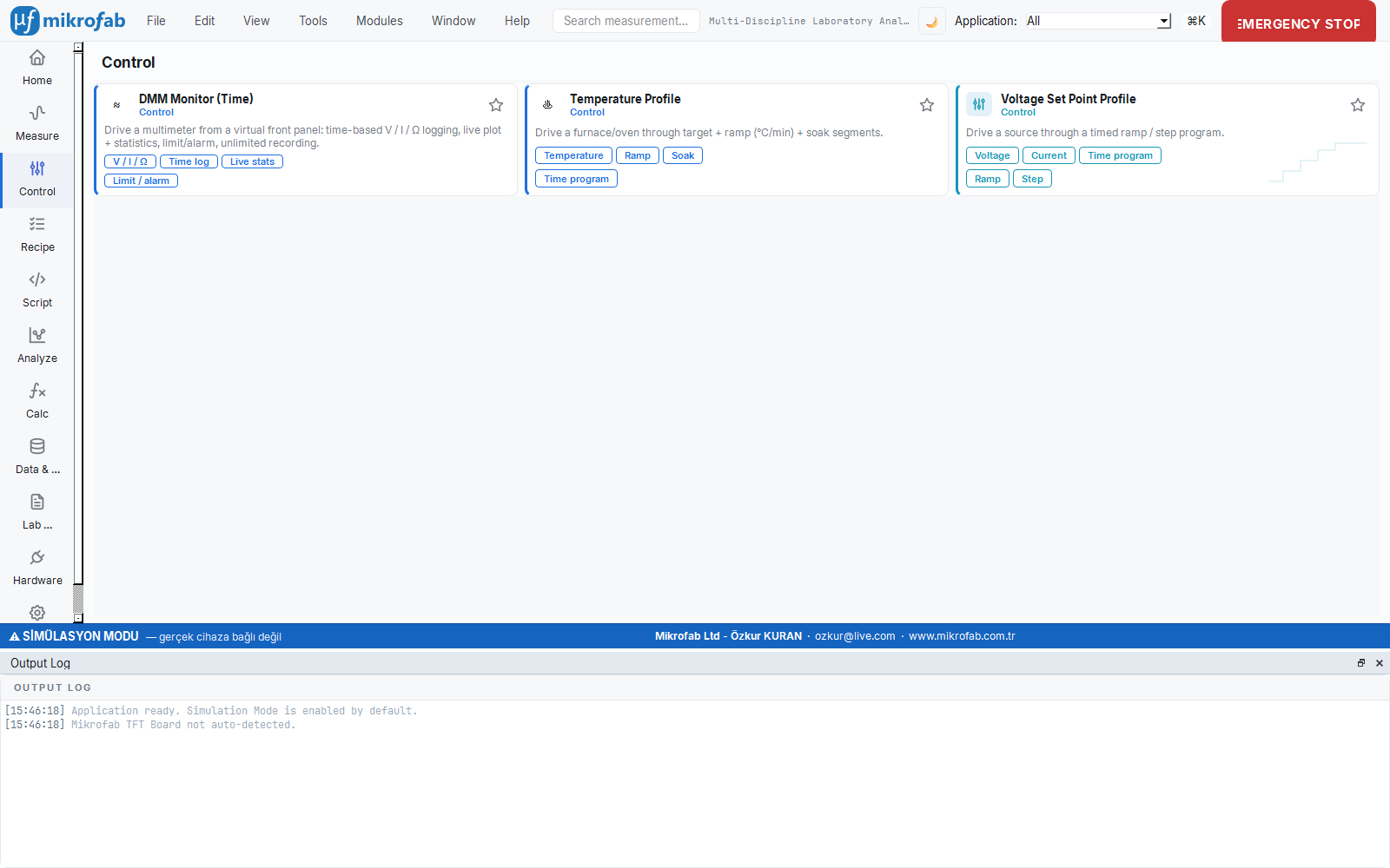
6. Device Roles and Assignment
Measurement modules require functions such as "source", "meter", "switch", "temperature"; the role system binds which physical device assumes which function. Like casting actors for the roles in a play — this way the measurement talks not to "Keithley 2614B" but to the abstract "SMU role".
- Why it is done: to make measurements independent of specific device models and to make swapping devices easy.
- What it teaches / measures: which device is assigned to each task (role) and that a clear warning is given if a role is missing.
- Where it is used: when setting up a multi-instrument bench, when swapping devices, when loading profiles.
The software solves the question of "which device does which job" with the role abstraction. There are two vocabularies.
6.1 Capability Roles (11 Canonical Roles)
The card-based Hardware page uses fine-grained 11 capability roles:
| Role | Abbrev. | Meaning |
|---|---|---|
| SOURCE | SRC | Voltage/current source |
| METER | MEAS | Current/voltage measurement |
| FOUR_WIRE | 4W | Kelvin / 4-wire sensing |
| SWITCH | SW | Routing / multiplexer |
| TEMPERATURE | TEMP | Temperature control/reading |
| MAGNETIC_FIELD | FB | Magnetic field |
| ELECTRIC_FIELD | FE | Electric field |
| LIGHT | LIGHT | Illumination / solar simulator |
| LOAD | LOAD | Electronic load |
| SPECTRAL | SPEC | Spectral analysis |
| SENSE | SENSE | Potentiometric / pH |
An SMU automatically provides the SOURCE + METER + FOUR_WIRE capabilities; the relay board provides SWITCH; the thermometer provides TEMPERATURE.
6.2 Legacy Device Roles
Measurement modules and the RoleBinding also use coarse device-level roles: SMU, RELAY_CONTROLLER, THERMOMETER, LOCK_IN, TEMPERATURE_CONTROLLER, DMM, DAQ, OSCILLOSCOPE. Each one expands into a capability set (e.g. SMU → {SOURCE, METER, FOUR_WIRE}).
6.3 Role Mapping (Role Mapping Tab)
In the Role Mapping tab of the Hardware page you assign a device from the inventory to each capability role. The assignment is saved instantly and the "N / 11" coverage indicator is updated. When a device is deleted, all roles pointing to that device are cleared automatically (so the resolver does not reference a missing device ID).
6.4 RoleBinding
When a measurement is started, the assignments are resolved into a single RoleBinding object: the primary fields smu, relay, thermometer + a capability access map. If a module cannot find a role it needs, a clear warning is raised with MissingHwRoleError (missing role).
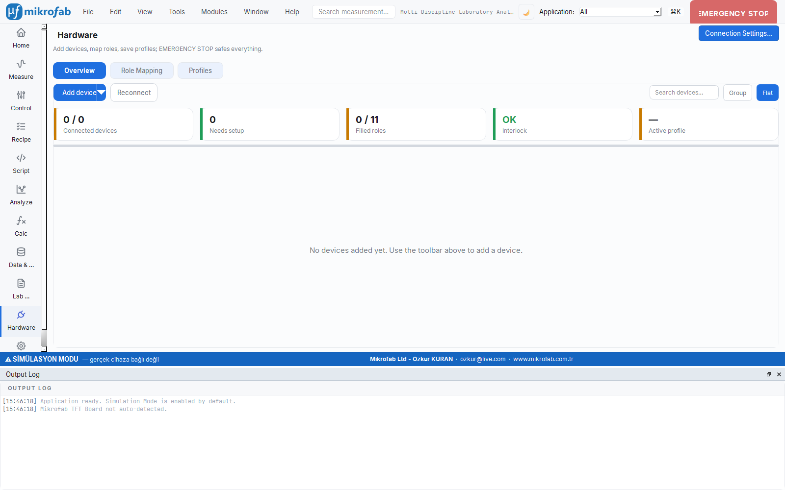
7. Card-Based Hardware Page
The Hardware page shows each device on the bench as a "card" carrying a colored status badge; this way you see the whole inventory, the connection state and the actions at a glance. Like the "on time/delayed/cancelled" board on a flight information display, it reports the current state of each device with color.
- Why it is done: to see and manage a multi-instrument bench from a single center.
- What it teaches / measures: device states (Connected/Pending/Error/Needs Setup) and the actions available per card.
- Where it is used: during setup, monitoring and troubleshooting.
The Hardware page shows the inventory as device cards and offers three tabs: Overview (cards + summary), Role Mapping, Profiles.
7.1 Device Cards and Status Badges
Each card shows the device's identity, capability chips and a status badge (status pill):
| Status | Meaning |
|---|---|
CONNECTED | *IDN? responded in the last probe |
PENDING | Discovered, not yet probed |
IDLE | Known-idle (default at startup) |
ERROR | Probe failed; last_error is stored |
NEEDS_SETUP | Undefined serial port / device unreachable during profile restore |
From the card action menu: Open panel (instrument console), Diagnose / Test, Self-test, Configure, Update firmware, Delete, Troubleshoot options are offered (depending on the device type).
7.2 Simulated Device Badge
Simulated devices carry a white SIM badge on a purple background on their cards. This badge is in a filled-pill form for contrast (WCAG AA). A simulated device is not a real connection: even if the instrument console is opened, the session_opened signal is not emitted and the card is never misleadingly painted as CONNECTED.
Adding simulated devices: the Add simulated button in the Add Device dialog adds a fixed set of mock devices that cover the bound capability roles (SMU 2614B, Switch Matrix, thermometer, DC supply, LCR, PV multiplexer, MFLI, Eurotherm, Sun EC10, K2000) — without any I/O.
7.3 Device Adding Paths
- Scan: a read-only discovery runs in the background; found candidates are checked and added.
- Add simulated: zero-I/O mock devices.
- RS-232 manual: port/baud/parity/stop +
*IDN?probe (§3.3).
During the scan an animated bar and an elapsed-time counter are shown; when the scan finishes, a "{n} devices found · {s} s" summary is written.
7.4 Save/Load Profile (Station Profiles)
You can save a device inventory and role assignments you have set up once as a named "station profile" and later restore it with a single click. Like a save file in a game; you will not have to set up the bench from scratch the next day.
- Why it is done: to eliminate repetitive setup work and ensure consistency.
- What it teaches / measures: which devices are ready and which are missing (
NEEDS_SETUP) when the profile is restored. - Where it is used: shared labs, quick switching between different experimental setups.
The Profiles tab saves/loads the current inventory + role assignment as a named station profile (config + .yml export/import). When restoring a profile the devices are re-polled; expected devices that are unreachable are flagged as NEEDS_SETUP (not an error — they are simply not on the bus right now) and the missing devices are summarized by name.
8. Device Configuration (Configure)
The Configure dialog lets you edit a device's connection settings (address, timeout, serial parameters such as baud/parity, and driver-specific options). Like a device's "settings" menu; each field warns immediately if an invalid value is entered.
- Why it is done: to fine-tune the device for correct and stable communication.
- What it teaches / measures: which settings are valid; if there is a live driver, the parameters are generated from a schema and constrained.
- Where it is used: when setting up serial devices, assigning an alias, resolving timeout issues.
A device's Configure dialog shows the identity read-only and offers editable connection fields. It performs no hardware I/O; on OK the owner (the Hardware page) applies the setting.
| Field | Type | Range / Option | Note |
|---|---|---|---|
| Alias | text | free | User-friendly logical name; preserved across device swaps (keeps role assignments) |
| Resource / bus | text | valid VISA/serial | Inline validation; if invalid, OK is disabled |
| Timeout | number | 500–30000 ms, step 500 | Default 3000 ms |
| Baud rate | list | 9600 / 19200 / 38400 / 57600 / 115200 | Enabled only on serial/ASRL resources |
| Parity | list | None(N) / Even(E) / Odd(O) / Mark(M) / Space(S) | Serial/ASRL only |
| Stop bits | list | 1 / 1.5 / 2 | Serial/ASRL only |
Dynamic schema form: if there is a live QCoDeS driver for the device, per-parameter fields are generated from the driver's parameter schema (get_parameter_schema()) (each with min/max bound validation). If there is no live driver, the basic form above is shown. All validation errors are shown inline (red label) and OK stays disabled until they are all cleared.
baudrate is dropped (so there is no data noise); probe_resource already applies baud only on serial resources.9. Instrument Console
The instrument console is a terminal window where you can send a raw command directly to a device (e.g. *IDN?) and see its response. Like having a one-on-one conversation with the device; it lets you test or manually drive the device without touching the measurement flow.
- Why it is done: to diagnose device behavior, try out commands and troubleshoot.
- What it teaches / measures: the difference between Write/Query/Read and the actual responses the device gives to commands.
- Where it is used: debugging, recognizing a new device, advanced manual control.
The instrument console is a separate top-level window per device, in the style of the NI-MAX "VISA Test Panel". You can send commands to one device while it is IDLE while a measurement continues on another device. All I/O runs off the GUI thread.

9.1 Generic Command Console
| Control | Description |
|---|---|
| Write | Writes the command (does not wait for a response) |
| Query | Writes the command + reads one line of response (Enter key = Query) |
| Read | Performs a read only |
| Identify | Queries *IDN? |
| Read STB | Reads the status byte (*STB?) |
| Clear Device | Device clear |
| Hex view | Show the response in hexadecimal (hex) |
| Clear Log | Clear the log (always enabled) |
Options row:
| Option | Unit | Range / Option | Default |
|---|---|---|---|
| Termination | — | \n (LF) / \r\n (CR+LF) / \r (CR) / None | LF |
| Bytes-to-read | bytes | 0 – 1,000,000 | 0 |
| Timeout | ms | 100 – 30000 | 3000 |
9.2 Session Lifecycle and Busy Protection
- When the window opens, a held session is opened (if the device is not busy). When a measurement starts using that device, the session is released, the body is disabled, and it is automatically reopened once the device is free again (~1 s busy polling).
- When a session against a real device is opened successfully,
session_openedis emitted and the card on the Hardware page is paintedCONNECTED(a successful open is positive proof of liveness). In a simulated session this is not emitted.
9.3 Switch Matrix (TFT Board) Console Body
A special body for the Switch Matrix adds TFT selection buttons on top of the full command console. Clicking a TFT: (1) sets the host's active TFT (the measurement reads this), (2) writes that TFT's relay command (None → "a") through the console and logs it. The SCPI quick-actions (Identify/STB/Clear Device) are hidden for the Switch Matrix because they are meaningless there (*IDN? would be parsed like a relay command).
10. Firmware Update
The embedded software (firmware) inside the Switch Matrix board is updated safely through a device card. Like refreshing a device's operating system; the software has safety gates that prevent the wrong board from being flashed by mistake.
- Why it is done: to keep the board software up to date with bug fixes / new features.
- What it teaches / measures: whether the board is the correct model (via
*IDN?) and whether the flash is safe. - Where it is used: initial setup, recovery flash, or firmware version upgrade.
The Switch Matrix board's Arduino firmware is updated through a device card (the port locked to that card's bus). This way an unrelated Arduino Mega board cannot be flashed by mistake.
10.1 Flow
- At startup the board's
*IDN?identity is read:- Matches the expected model → green note, Flash enabled.
- Different (non-empty) model → Flash is blocked (wrong board on this port).
- No response (empty/old firmware) → Flash allowed (first/recovery flash).
- avrdude writes the shipped pre-compiled
.hexto the board (no Arduino tool needed on the target), with a live log streaming. - After the flash it is re-validated with
*IDN?.
10.2 Board and Tool Parameters
| Parameter | Value |
|---|---|
| Board | Arduino Mega 2560 (atmega2560, programmer wiring, 115200 baud) |
| Firmware image | tft_switchmatrix_mega2560.hex |
| Expected IDN model | TFT-SWITCHMATRIX-16 |
| Shipped firmware version | 3.0.0 |
avrdude is searched for in this order: the MIKROFAB_AVRDUDE environment variable → the tools/avrdude/win/ shipped with the product → the Arduino15 package → PATH. Every real flash is bounded by a timeout (default 120 s). In mock mode no subprocess/serial I/O runs; a short synthetic log streams and success is reported.
FIRMWARE_REGISTRY) receive a flash action. This is the safety gate that keeps the flash away from unrelated Arduino Mega boards (e.g. the pv_mux 40-channel board) — the wrong image would brick the board.11. Device Profiles (Catalog)
A device states its identity via *IDN? but does not state capability information such as accuracy class or maximum voltage/current; these come from a machine-readable catalog. Think of it as the device's technical data sheet — the resolver scores the most suitable device for a task by looking at these data sheets.
- Why it is done: to automatically select the most suitable device among candidates for a role.
- What it teaches / measures: the source/measure envelopes of devices and their class priorities (these are not safety limits).
- Where it is used: when mapping devices to roles, in selection decisions on a multi-instrument bench.
The identity (*IDN?) can be read from the device; however the accuracy class and device class cannot be queried via SCPI. These come from a catalog, keyed by model, that is built at import time from a machine-readable registry (specs/device_specs.json). The resolver scores candidate devices for a slot with the following inputs:
- Capabilities (fine leaves) — hard filter.
- Device class + class priority (ordering by the precision / constant / fast preference).
- Source/measure envelopes (
v_max,i_max, resolution) — range filtering + quality scoring.
An unknown model falls back to a safe default built from the capabilities reported by the inventory; values measured via SCPI at connection time are overlaid on the catalog (apply_probe). None of these numeric values are safety limits — safety limits live in the device_safety layer.
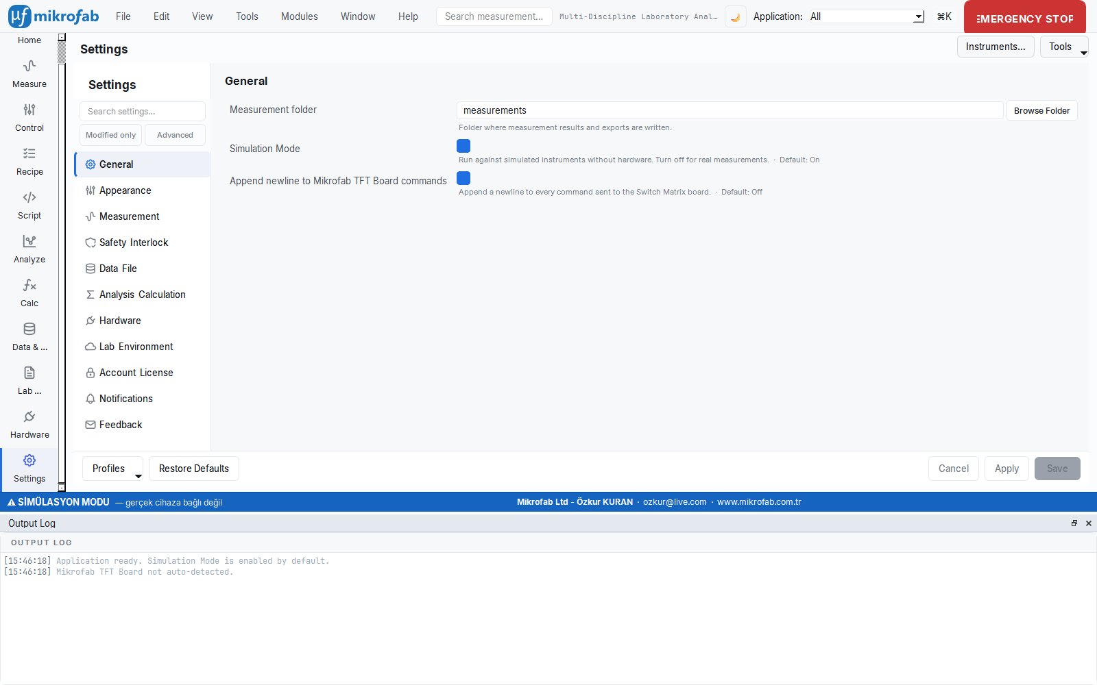
12. Mock (Simulation) Mode
Simulation mode runs the entire software with fake but realistic devices, without any real device connected. Like a flight simulator: you can safely learn and try discovery, connection, role assignment and measurement without being at the bench.
- Why it is done: for hardware-free learning, demos, development and testing; without risking a real device.
- What it teaches / measures: the exact same interface as a real bench; only the data is generated from a physics-mock.
- Where it is used: training, getting to know the interface, automated tests; switching to reality is a single checkbox.
Simulation mode is for hardware-free development, demos and testing. The backend is the canonical physics-mock MockSMUDriver.
12.1 Behavior
- The driver always reports "connected" (
connected == True) and returns a valid IDN:MOCK,<vendor>, <model>,0,0.1. - A single-channel model raises
ValueErrorwhenchannel="b"is requested; a dual-channel model supports bothaandb. send_rawproduces reasonable fake responses (*IDN?→ mock IDN; other queries →MOCK:0); the console/soft-panel is fully functional in mock.run_self_testreturns PASS instantly (there is nothing real to test).
12.2 Mock Physics Profiles
The fake device in simulation does not generate data randomly but according to real physics equations: a diode behaves like a diode, a solar cell behaves like a cell responding to light. Like a realistic computer game engine, it produces the curve of whichever device profile you choose.
- Why it is done: to produce meaningful, physically consistent curves in a hardware-free environment and to test analyses.
- What it teaches / measures: the output according to the profile type (TFT transfer curve, diode equation, solar cell I–V).
- Where it is used: testing analysis modules, generating training material, demos.
The mock measurement physics is driven by a profile:
| Profile type | Behavior |
|---|---|
None (default) | TFT/FET: drain (a) output/transfer curve, gate (b) small leakage current |
diode | Physical diode/Schottky single-diode equation (I0, n, R_s, R_sh, T_K) + noise |
solar_cell | Single-diode solar cell: I = Iph − I_dark(V); Iph proportional to irradiance |
Iph, diode parameters) → I = Iph·(E/1000) − I_dark(V) → Output current (A). Here E is irradiance (W/m²), with 1000 W/m² taken as the reference (1-Sun). In current-source mode, the voltage corresponding to the target current is solved by bisection.12.3 Simulated Badge
All simulated devices/sessions are explicitly labeled as SIM in the interface (§7.2) and do not behave like a real connection. When switching from mock to real you only clear the Simulation checkbox and enter a valid address; the interface is the same.
13. Safe Connection, Timeout and Safe State
All code that talks to the hardware obeys immutable safety rules: every command is made with a time limit (timeout) and, on error/shutdown, devices are brought to a safe state (output is turned off first, then relays opened, then the connection closed). Like the "turn off the gas when you leave" rule in a lab, the sample and the device are protected even in abnormal situations.
- Why it is done: to protect the hardware, the sample and the user from risks such as lock-ups or over-driving.
- What it teaches / measures: the timeout limits and the safe-state sequence; that errors are not swallowed but surfaced.
- Where it is used: in every measurement session; especially on cancel, error or unexpected shutdown.
All code that talks to the hardware obeys immutable safety rules (the device-communication standard):
13.1 Timeout Mandatory
Every read/write/query going to a device is made with a bounded timeout; there is no infinite/blocking wait. Key limits:
| Location | Unit | Value |
|---|---|---|
| VISA resource open (discovery) | ms | 1500 |
| Discovery probe wall-clock | s | 8.0 |
| Default VISA timeout | ms | 3000 |
| Console timeout range | ms | 100 – 30000 |
| Switch Matrix read | s | 2.0 |
| Firmware flash | s | 120 |
visa_timeout_ms and the general timeout values are managed here.13.2 Safe State Preserved
On error, cancel or shutdown the outputs/biases are brought to a safe value. The sequence:
- SMU output OFF (
output_all_off), - Switch Matrix opens all relays (
a), - Safe closing of the connections.
This sequence runs not only in the Qt closeEvent but also at interpreter exit (atexit) and on an uncaught exception (excepthook); this way abnormal terminations are also covered.
13.3 Mock Mode Not Broken
Every path that adds real I/O preserves its mock counterpart; the tests pass without hardware.
13.4 Error Checking
After SCPI/TSP operations the device error/status queue is checked; errors are not swallowed but surfaced meaningfully (e.g. read_error_queue, Switch Matrix drain_errors).
secure_connection field (TLS/SSH) is currently a placeholder; it is reserved for a future secure transport and is off by default in the current version.Summary
In this chapter we covered: multi-vendor device support and *IDN? model matching; VISA interfaces, automatic/periodic discovery and timeout protections; the three SMU setup modes; the Switch Matrix relay board (token + SCPI, all-off a, route verification); device roles and assignment; card-based inventory, status badges and the simulated badge; device configuration; the instrument console; firmware update; device profiles/catalog; the mock physics mode; and the safe-state/timeout principles. All these features can be used first in simulation, then on a real bench with the same interface.